-
#60
by
fspGTD
on 14 Mar, 2006 22:31
-
Biobill: The component below R2 and R3 looks like a diode to me. I'd guess it's a zener diode type, because of it's label ("ZD1").
All: keep up the great work going on in this thread!

-
#61
by
regcheeseman
on 15 Mar, 2006 07:29
-
That TI circuit is exactly the same! (Johnny you may have a chance if you get me images of both side of board)
But for BIOBILL I'm reckoning; using the designations on your board...
Swap R1 for 15K
Remove R2
Remove R3
Swap R4 for 191 ohm
Swap R5 for 72 ohm
Swap R6 for 100 ohm
Swap R7 for 10K
Replace zener with wire link
Swap C1 for 10nF
Swap C2 for 47nF (nanofarad)
Swap C3 for 47uF (microfarad)
Swap C4 for 3.3uF
If replacing C3 or C4 with electrolytics then observe polarity as marked on board.
-
#62
by
biobill
on 15 Mar, 2006 11:40
-
Thanks guys for the thread and the specific help. I've added my sketch of the schematic in my post above in hopes that it will help others (hopefully I got it right). I'll make the changes to the board, get the gauges back in the car and let everybody know how it works. Any guess on how much "calibration" will be involved? I'm guessing that's what the variable resistor is for.
I'm wondering if it's worth it to get a gauge overlay to expand the scale. I'm thinking for now I should just see if I can get it to work, and

oh yah
get the diesel swapped into the Cabriolet before summer gets here!
-
#63
by
regcheeseman
on 15 Mar, 2006 12:23
-
I'm wondering if it's worth it to get a gauge overlay to expand the scale. I'm thinking for now I should just see if I can get it to work
You can use the variable to calibrate it to work with either the gasser or diesel scale.
Here's your PCB image reworked..

And a 5 minute lash up of your schematic - some differences to your version.

16 mar - schematic edited for additional line between pin 1 and GND - sorry!
-
#64
by
YoSono
on 15 Mar, 2006 17:09
-
In response to all the great work that Reg & Fatmobile are doing, i decided to redraw some stock looking Tacho faces that are in relation to the diesel rev range - inspired by the mk2 GTD tacho clocks. The NA spec one was more tricky to do than the euro one, but if your a sucker for factory fresh looking details, then hopefully you'll enjoy these as much as me.
If anyone wants a high-res printable version (they are all to scale, and the correct size, all you need to do i press print! or get someone to print em for ya) then drop me a PM, and i'll get back to you
cheers y'all
lee.
-
#65
by
RabbitGTDguy
on 15 Mar, 2006 18:51
-
man...those look great!
I would like to rework a set of the early clocks for MK1 with the gasser tacho... they are roundies...but would be cool with the correct tach readout.
Anyone good with that kind of magic?
I have similar NA versions in "white faced" units with corrected rpm range for a diesel on the westy style clusters. Also has a Rabbit symbol and "GTD" on them as well. Tim Cooper made them a while back...
Joe
-
#66
by
mortskeg
on 15 Mar, 2006 23:22
-
Ah Central Lee!
Now I know that YoSono=Lee. Very nice. You are the man; keep up the good work.
-
#67
by
fatmobile
on 16 Mar, 2006 02:52
-
regcheeseman,
Great work. It looks like you have this circuit figured out. Doesn't seem like it takes you much time after looking at the circuit to have it drawn up and posted. Glad you came along or for me it would still be scribblings on paper.
I got the instrument cluster out of my '83 Gti and it looks just like mortskeg's.
I'd like to run my engine up a little higher than stock RPMs. Is there a way to get it to register 6000 RPM or to match the scale of the stock gasser tach?
@ fastmobile Is this maybe the first european tach you see ?
You talking to me? fastmobile ha. I like it ... might have to change my name. :lol:
That is the first euro tach I've seen.
-
#68
by
regcheeseman
on 16 Mar, 2006 04:41
-
fatmobile,
Will run to 6K no problem - as long as your engine can!
-
#69
by
johnny
on 16 Mar, 2006 06:42
-
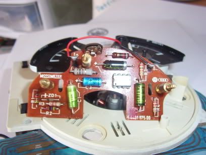
Here is the schematic of my gastach, I hope it is usefull.


For bigger pictures you can click the following link:
http://gallery.vwcaddyforum.nl/displayimage.php?album=214&pos=47I've seen a lot of similarity with the tach of Biobill, I think I'm getting the hang of it :lol:
Some numbers:
tachnumber: MOTOMETER 54401 201 00
chip: sn29736p 627x
c1: U7 10%
c2: U9 100V MKT1813
c3 and c4:U9 10V 22µ
v1: ZPD 68
variable: 22K
r1 - r7: I really don't have a clue
Let me know if you need more info, I really appriciate all the help
@fatmobile: sorry, but fastmobile also sounds great :oops:
-
#70
by
regcheeseman
on 16 Mar, 2006 08:44
-
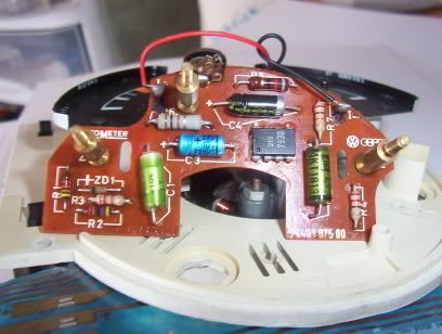
Johnny,
Could you just turn the board over and take a photo at the same scale?
It makes my job MUCH easier!
Also, the numbers you have written on the components, are they the ones actually printed on the board?
-
#71
by
RabbitGTDguy
on 16 Mar, 2006 10:56
-
I'll have to get cleaner pics later... but here is the board of an early German motometer tacho... 77-80 style... gas
For those that might like to add the tacho to their setup. This is the one I'd like to use...
My camera batteries just died...so i'll have to update pics later...
What did you think of that TDI crank sensor shot I posted?
Joe
-
#72
by
regcheeseman
on 16 Mar, 2006 11:17
-
do you have a flash on that camera?
And could you put it into macro mode (little flower button) and get a bit closer?
As for the TDI crank sensor, I reckon the standard gasser tacho may cope with that setup with some small screwdriver tweaks. You will have to use an amplifier circuit (4crawler link) to fit between sensor and tacho though.
-
#73
by
RabbitGTDguy
on 16 Mar, 2006 11:32
-
There...updated, just replaced the previous ones I had taken above... I can try again later if those don't work...
As for the amplifier and using the regular tach... that'd be interesting.. Is that the one you get from Dakota Digital? I know they have a "W" interface, but I'll have to read through and see if they also are the ones that carrier the amplifier that you are speaking of. Would be nice to use the stock sensor...if not though, i may modify this tach i have pictured to work on the W terminal...
Joe
-
#74
by
johnny
on 16 Mar, 2006 13:36
-
Johnny,
Could you just turn the board over and take a photo at the same scale?
It makes my job MUCH easier!
Also, the numbers you have written on the components, are they the ones actually printed on the board?
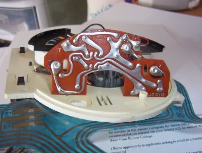
Here's a picture of the back of the board.

And I made a layover of the back on the front of the board (Hoping to take some work out of your hands.

The numbers on the components are exactly the same numbers as on the board.
(Is there also a regcheeseman fanclub, I would like to be part of it :lol: )

