-
#120
by
fatmobile
on 07 Apr, 2006 23:06
-
I put everything back together and plugged it in ... nothing.
I traced the wire from the alternator and it was hooked up right so I swapped a jumper in place of the diode on the input side of things and I now have a working tach in my '91 Golf (gasser turned into a turbo diesel).
I drilled a hole in the front of my instrument cluster so I could adjust it while it's in the car. I ended up adjusting it all the way to the bottom end but I have rigged up a 90 amp, non-AC setup and used a slightly larger pully.
It's close but I think it's reading about 500 RPM higher on the top end than it really is.
I did some things different. Pin 1 is grounded and has a 10nf cap to pin 2.
No C3 cap to positive power.
Pin 6 is grounded so there is no R4.
R6 the parallel resistor is 5.2K.
R2 is 82 ohm
I'll draw something up and post it.
Ha, I have a tach


-
#121
by
regcheeseman
on 10 Apr, 2006 04:24
-
I look out for your schematic, Not sure about somre of your changes from a functioning circuit.
The lack of adjustment is either down to the missing R4 or the your R6 change which is not a parallel - I think I know what you've done but R6 should still be present and it has to be in series :?
Anyway it works.
-
#122
by
fatmobile
on 11 Apr, 2006 03:48
-
Ok, you are right.
There is still a resistor in series with RV1.
I kept the 15k resistor that was there originally. I might swap it to the 13k value the diesel tach had, to see if I can get the adjustment to ride closer to the middle instead of bottoming out.
I forgot we were going to name the parallel resistor something else... Rx?
I almost have the corrected drawing of the original gasser tach done.
I will show what I did but now that I understand the RC circuit better, I probably could have gotten by with fewer changes so I'm going to grab another instrument cluster from the '91 Golf they hold for me at the local salvage yard and do minimal changes then check to see what they did.
On a side note... now my clock doesn't work, ha.
Now I don't know exactly when I'm driving too fast :lol: but I know my RPMs.
-
#123
by
fspGTD
on 12 Apr, 2006 17:11
-
regcheeseman - I definitey agree that there is some new FAQ worthy material in this thread!
Feel free to go ahead and create a new thread in the FAQ section about tachometer conversions. Feel free in addition to summarizing/condensing the most pertinent material contained in this thread, to include links to this thread and any other possibly useful, related threads. Thanks!
-
#124
by
Mark(The Miser)UK
on 13 Apr, 2006 08:42
-
Well done Reg
I never did dig out that osciliscope

All it took was someone with a little nouse...
Who'd of thought that Cornwall could produce anything other than Pasties...
:twisted: Now you're gonna cost the sensor sellers serious $$=££ :twisted:
All I have to say from here is
Ooooh Arrrrrh
:shock:
-
#125
by
RabbitJockey
on 07 Aug, 2006 21:21
-
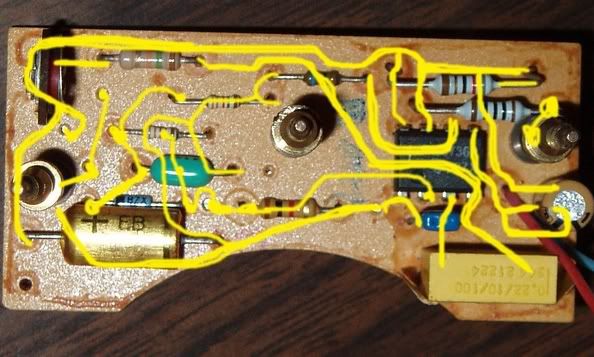
my late cabriolet cluster arrived today (fits perfectly into a mk1 jetta) so i started tearing into it, i thought it would be just like the vdo one in the faq, but mine is slightly different, here are pictures of both sides of the circuit board, any help is well appreciated
mine:
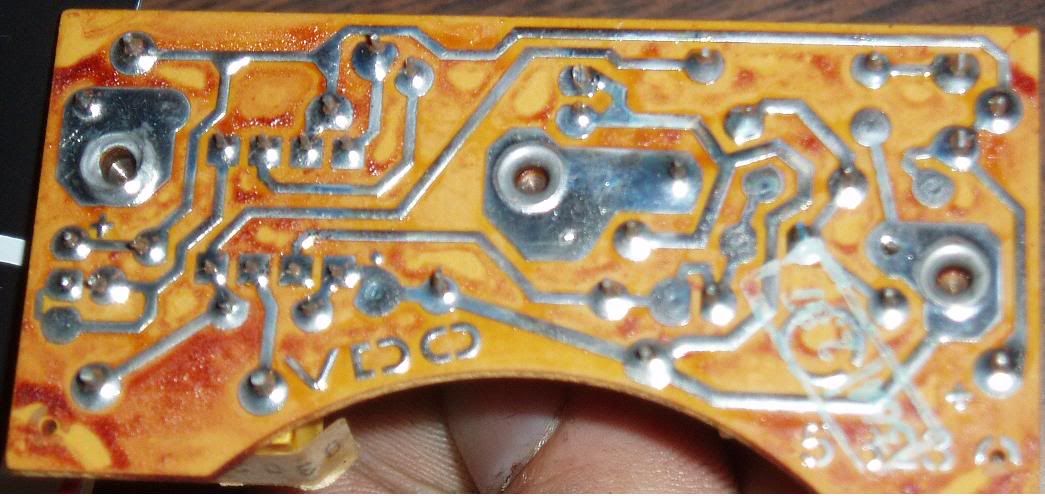
pictures from faq:

-
#126
by
RabbitJockey
on 07 Aug, 2006 22:03
-
actually, now that i have been looking, it appears that i may just be able to do more or less the same mods, well jsut try and make my board like the finished one for the similar but different tach. i dunno though, it would be quite handy if someone who knew would give me a post, thanks for any help. :wink:
-
#127
by
fatmobile
on 08 Aug, 2006 03:51
-
I've been messing with another '91 tach I got.
The first thing to do is make the input to the chip match the TD tach.
The input comes into pin 2. Looks fom here like it goes to the little blue diode with the B7X on it.... swap that for a straight through jumper wire.
That stuff is in the center. After that it's hard to figure out because the pics are too big for the screen and to look at stuff I have to scroll right, take a look, go down scroll left. Would be nice if all the stuff stayed on the same end of the board. Flipping it vertically would make it easier for me to follow.
It kinda looks like the resistor above the greeny/blue blimp (cap), brown, red?, brown, light brown, light brown, BRBBB? is the one that needs swapped to 15k ohms.brown, green, orange.
It's possible that the only other change would be swapping the big yellow box (resistor) in the lower right corner needs to be swapped with a cap that says 473 on it. (47 nf).
Try that and see what happens.
On my first tach I swapped out way more than was needed. On the last one I swapped a little more than just the diode and resistor on the input. That brown, black, red resistor got swapped for a cap. 10nf (103 on it). Not sure this needed done because I was messing around with a 15k resistor on the tach side and changed too many things at the same time.
-
#128
by
RabbitJockey
on 08 Aug, 2006 18:34
-
-
#129
by
fatmobile
on 09 Aug, 2006 04:25
-

The red line shows the path the input signal takes to get to the chip. That needs to be 15k ohms. Chuck the diode and swap a jumper in it's place.
Change the resistor to 15k.
-
#130
by
regcheeseman
on 09 Aug, 2006 04:49
-

With reference to my final diesel schematic and the image above
Remove all components marked with red X
Replace D1 with wire link
Replace R10 with 10nF capacitor (C1)
Replace RV2 with 47nF capacitor (C5)
There is no provision to place capacitor C3 - Should work without but you may want to put one in if the needle is prone eratic behaviour.

-
#131
by
RabbitJockey
on 09 Aug, 2006 20:10
-
accidentally touched the positive to the signal, but it wasn't grounded, but the signal wire was connected to the alternator, but the car was not on, i dunno if this could have blow it or not,... we'll see
-
#132
by
RabbitJockey
on 09 Aug, 2006 20:39
-
never mind i got it working and it's pimp, just need to actually get it into my car now
-
#133
by
RabbitJockey
on 09 Aug, 2006 21:32
-
yay
-
#134
by
fatmobile
on 10 Aug, 2006 00:49
-
I don't know about having to remove the components with the red Xs.
trevOrbr, what all did you change?
RV2 isn't variable so should it have an R designation instead of the RV?