-
#105
by
ToddA1
on 22 Feb, 2011 02:26
-
Has anyone else completed jimbote's method with the Ford VSS? Something I didn't see mentioned was how far apart the nuts added to the crank pulley need to be. I'm sure the closer to the center they are, the higher the rpm would read.
-Todd
-
#106
by
jimbote
on 15 Mar, 2011 14:12
-
Has anyone else completed jimbote's method with the Ford VSS? Something I didn't see mentioned was how far apart the nuts added to the crank pulley need to be. I'm sure the closer to the center they are, the higher the rpm would read.
-Todd
Todd...the nuts need to be at the edge of the pulley so they can induce a current in the pickup....it will make no difference in RPM whether they're near the center or on the edge....just two pulses per revolution is all that matters...but they must be positioned so they sweep very closely to the sensor....are you having an issue mounting them at the edge?
-
#107
by
ToddA1
on 15 Mar, 2011 14:23
-
No issues with mounting them, but I wanted to know before I mounted them.... just in case.
I forgot to order than sensor with my last parts order, but it'll get done. I want an actual tach signal for my remote starter.... I don't like relying on voltage sensing.
Thanks.
-Todd
-
#108
by
Powered by Spearco
on 22 May, 2011 19:43
-
I just wanted to say thanks for the info on the Ford sensor. It works on my Autometer tach.
-
#109
by
srgtlord
on 13 Aug, 2013 19:36
-
-
#110
by
RabbitJockey
on 15 Aug, 2013 04:25
-
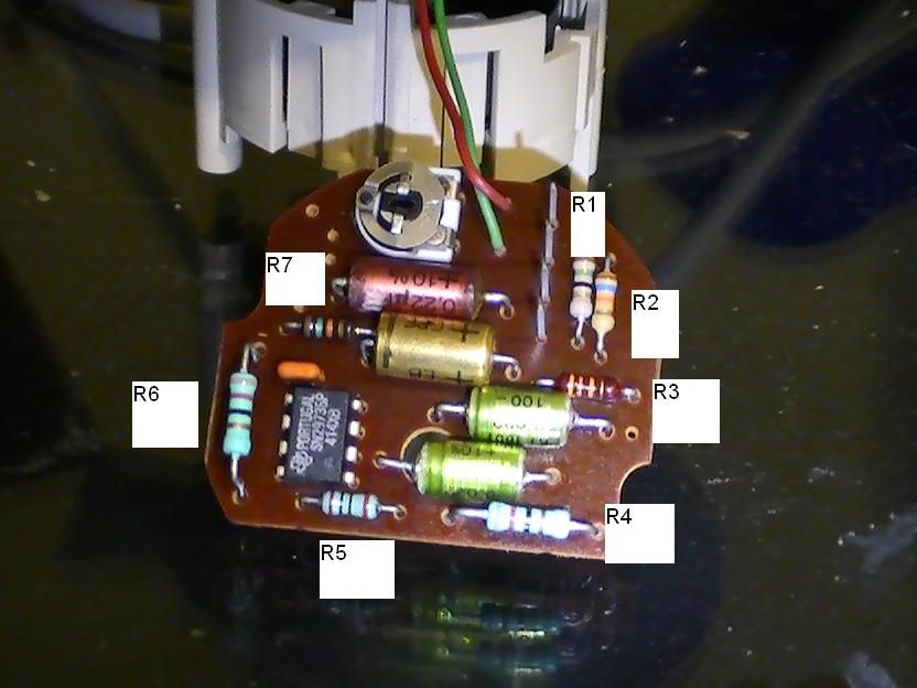
most of them have pretty similar schematics, take a picture of the other side of the board so we can see the traces.
-
#111
by
srgtlord
on 15 Aug, 2013 04:55
-
Ill take a picture, but I think I figured it out. This has an almost identical set of components to the first VDO gasser tach in the thread. I started tracing components and resistors and there are only 2 resistors that are different, one is 200 ohms and the other is 16 kilo ohms on my board. I do beleive the 16 kilo ohms coincides with r5 which has a dunno as the resistance label. The 200 ohm coincides with 162.
Ill double check on the capacitors but it looks like they are all the same. Its odd how VW decided to change the two resistors.
I think by following the conversion schematic for the first VDO gauge I should be in the ballpark of a working tach.
-
#112
by
RabbitJockey
on 15 Aug, 2013 08:57
-
basically if you can make what u have match the td circuit that regcheeseman posted then it should work, i've done it before on boards no one had converted, i think i posted one a few pages back
-
#113
by
srgtlord
on 15 Aug, 2013 09:38
-
Thats exactly what I was thinking

Looks like Ill be starting in on this tonight
-
#114
by
CrAzY_DrIveR
on 16 Sep, 2013 14:17
-
-
#115
by
R.O.R-2.0
on 20 Oct, 2013 13:12
-
-
#116
by
srgtlord
on 21 Oct, 2013 12:56
-
Well believe it or not..IT WORKS! and yes this is a 1985 gasser VDO tach
-
#117
by
RabbitJockey
on 25 Oct, 2013 08:10
-
they all look a bit different, but they are all quite similar, and they are all very simple circuits. it would be quite easy to just build the board yourself if so long as you could find the correct chip.
-
#118
by
RabbitJockey
on 25 Oct, 2013 08:11
-
actually can you confirm all the numbers on that chip?

specifically sn29736p?
?
-
#119
by
srgtlord
on 25 Oct, 2013 09:56
-
Unfortunately the only picture I have is the one I posted and the tach is currently installed in the car at the moment

When I go to calibrate the tach Ill pull the tach out of the cluster to get another look at the part number but this probably wont happen until spring.....
 [/URL
[/URL 
 [/URL
[/URL 