I wanted red LED's after seeing THIS link... DO READ THE LINK
http://forums.vwvortex.com/zerothread?id=4206297
You can do what he did or you can do a "better"  DIY and do it my way!
Be careful should you choose to just follow that thread. Your LEDs are very specific to amperage so unless you get exactly the same ones he did you will need to calculate what resistance you want.
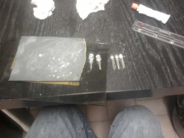
Supplies!
Very small gauge wire. I'd say 22.
a soldering iron with solder
LED's of course!
resistors - see the
RED TEXT at the bottom of this page to figure out what resistors you need
a dremel with a grinding stone and cutting disks (not essential)
emery cloth (80grit) and wet dry (240?) can replace the dremel, they are just slower. Totally up to you what grits you want.
and wire strippers of course[/list]
Here are some useful pics from the thread I stole this from
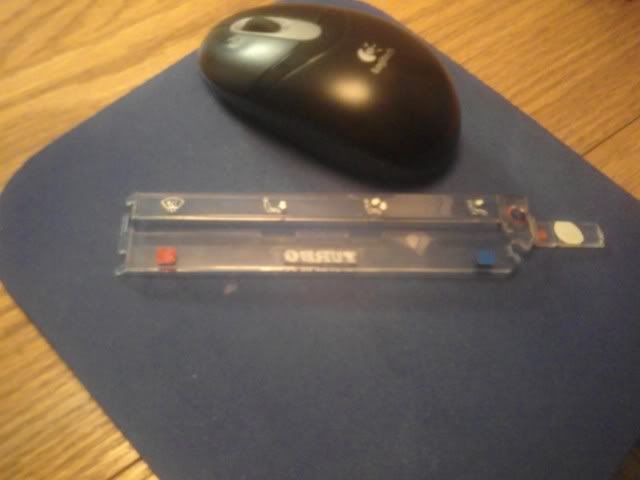
 And for my pics!
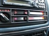
I painted the backing of the heater control panel semi-gloss black.
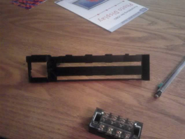
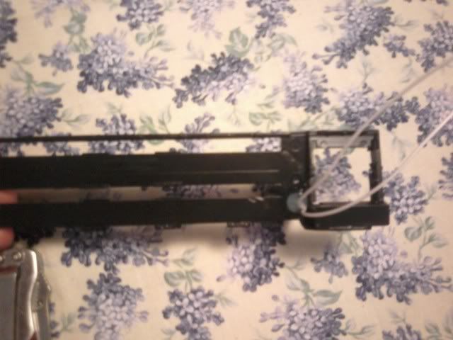
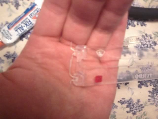
I dremeled out three spots for LED's in the graphics plastic piece UNLIKE the DIY link i posted up top. The hole circled in RED is where the old light used to go. The wires will now go through this hole.
And just one here... because they are in the same place when you put it together.
This is straight from the original thread. Solder wires to the pins that you pulled from the control unit and put them back in.
I used elmer's all purpose glue. Phew that stuff stinks!
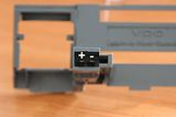
BE EXTRA SURE TO GLUE THE LED'S IN THE RIGHT WAY!!! Look at the LED polarity pic.
you want to link them + to -, + to - and so on. Make sense?
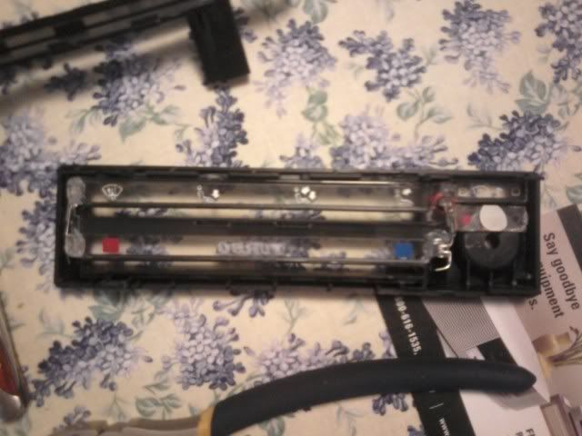
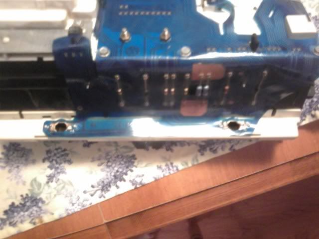
Unfortunately i didn't take a pic of my wires soldered in with the resistors
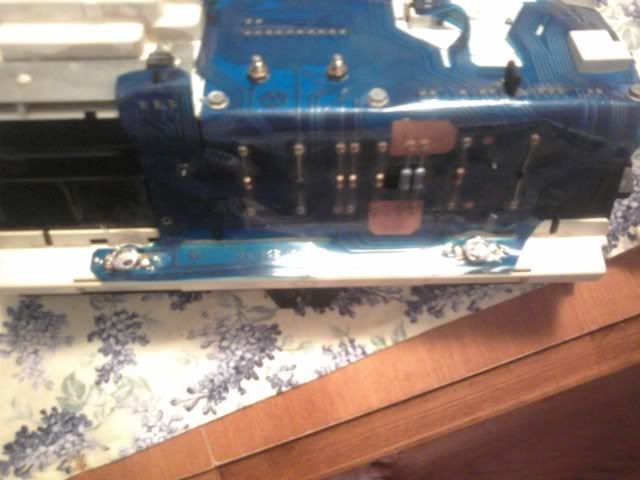
but i had my resistors running along the very bottom of the unit as displayed here
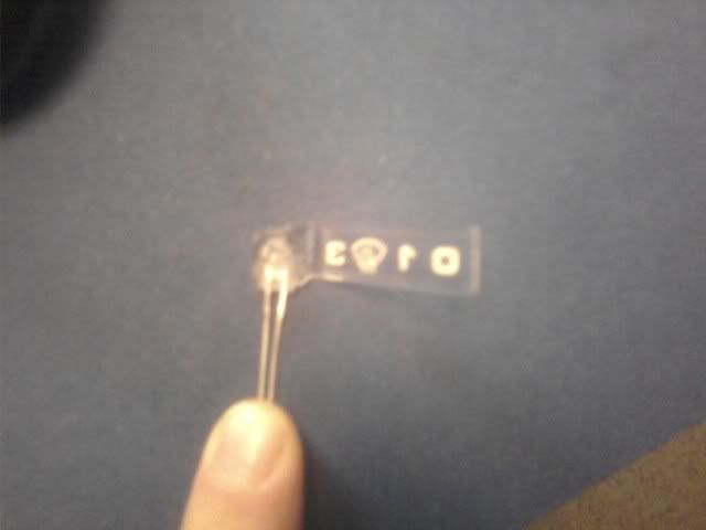
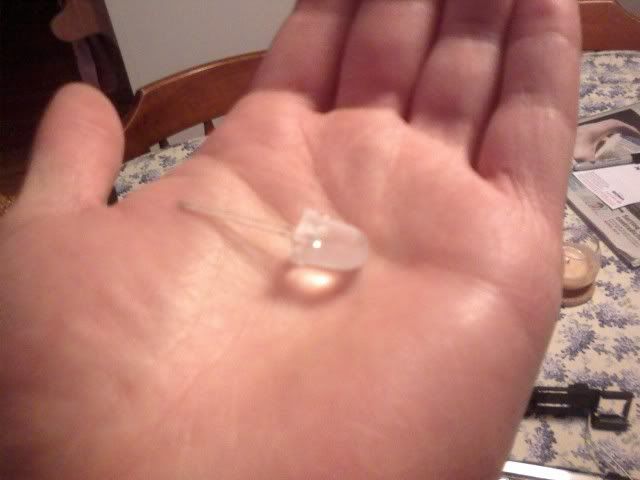
I used a dremel to get the 10mm LED's i used to a usable size and then sanded them to shape.
The glass gives a flat finish. The 240 i used left them a little cloudy. You may want to use or polish with 500.
a couple pics of the cut outs

and the 10mm LED
The Dash cluster unit was very very easy. I sanded the 10mm LED's to fit into where the other light fixtures went and they wedged in nicely.
A very important bit of info here is that each light on the dash here seems to get it's own power? I may be wrong but that is what i found.
so i resisted each LED down to 22 milliamps (per my LED's yours will be different).
My point is, i tried putting 1 resistor in the series and the non-resisted LED burnt instantly.
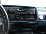
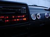
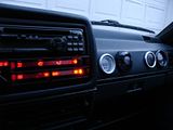
And here it is buttoned together!
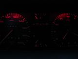
The dash was a bit dimmer with only two LED's but i can read it clearly.
The 4 LED set up is extremely bright with 48k LED's.
I added a switch to my gauge lights so that i can turn them off on long drives and
my passenger doesn't want to be annoyed by them at night.
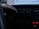
You can do this for the heater control too if you like!
Anywho, I hope this is useful to at least someone. I'm happy with it.
If you're unsure about resistor values just PM me OR use this formula
V*=IR
I = current (My LED's are rated for 22 miliamps +/- 5)
V = voltage (12V for us!)
R = resistance (What resistor value you need)
so my example is...
(LED's are rated in Milliamps. http://www.simetric.co.uk/siprefix.htm)
NOW, each of my LED's are rated to drop 2V per LED in the series.
You really need to be EXACTLY SURE what your LED's are rated for!
V*=IR
Voltage
V = 12V - (4 LED's * 2v each = 8v)
V* = 4V (this is the V you use in the formula because it is the Voltage WITH the drop incorporated)
Current
I = 0.022 Amps (given from LED rating)
Resistance
Is determined by your amperage and voltage drop. So this is dependent on what LED's you use.
My example is...
4V = (0.022)(R)
R= 4/0.22
R = 181 ohms.
Any value close to this works fine. It's better to OVER resist than to under resist.
So i chose two 100 ohm resistors to get a total of 200 ohms.And there we have it.
Cheers,
Ed[/list]
 Topic: DIY Dash LED's (Read 15527 times)